前置条件
Linux环境:Ubuntu 20.04
安装ROS2:foxy或者rolling,尽量安装最新版
安装gazebo:目前最新的是11版
参考链接:
Model目录的建立
创建model文件夹
mkdir -p ~/.gazebo/model/my_robot创建一个model config文件
gedit ~/.gazebo/models/my_robot/model.config向文件中添加以下内容
1
2
3
4
5
6
7
8
9
10
11
12
13
14
15
<?xml version="1.0"?>
<model>
<name>My Robot</name>
<version>1.0</version>
<sdf version='1.4'>model.sdf</sdf>
<author>
<name>My Name</name>
<email>me@my.email</email>
</author>
<description>
My awesome robot.
</description>
</model>创建model.sdf文件,该文件提供了创建一个机器人模型实例所需要的标签
1
gedit ~/.gazebo/models/my_robot/model.sdf
向上述文件中添加以下内容
1
2
3
4
5
<?xml version='1.0'?>
<sdf version='1.4'>
<model name="my_robot">
</model>
</sdf>
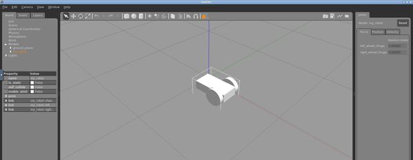
创建模型(model)
创建机器人的主体
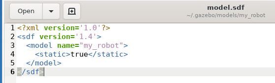
在创建机器人的时候,我们希望Gazebo的physics engine能够忽略这个机器人,那么在标签
下添加 true ,如上图 接着,在
true 标签下,添加以下内容 1
2
3
4
5
6
7
8
9
10
11
12
13
14
15
16
17
18
19<link name='chassis'>
<pose>0 0 .1 0 0 0</pose>
<collision name='collision'>
<geometry>
<box>
<size>.4 .2 .1</size>
</box>
</geometry>
</collision>
<visual name='visual'>
<geometry>
<box>
<size>.4 .2 .1</size>
</box>
</geometry>
</visual>
</link>最终model.sdf如下
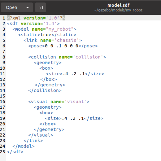
这样我们就创建了一个box,它的名字(link name)是‘chassis’
chassis的pose标签
- pose代表的是chassis几何中心的位置(x = 0 meters, y = 0 meters, z = .01meters)以及它的姿态(roll = 0 radians, pitch = 0 radians, yaw = 0 radians)。
- roll:绕x轴旋转
- pitch:绕y轴旋转
- yaw:绕z轴旋转
- pose代表的是chassis几何中心的位置(x = 0 meters, y = 0 meters, z = .01meters)以及它的姿态(roll = 0 radians, pitch = 0 radians, yaw = 0 radians)。
collision标签和visusal标签
- collision定义了几何形状,它将被Gazebo的collision detection engine所使用。
- visual定义了机器人的显示形状,它将被Gazebo的rendering engine所使用
- 大多数情况下这两个tag是一直的
添加一个caster wheel
caster wheel将被设计为一个半径0.05米的圆球
编辑model.sdf文件,添加如下内容(在第一个之后,之前)
gedit ~/.gazebo/models/my_robot/model.sdf1
2
3
4
5
6
7
8
9
10
11
12
13
14
15
16
17
18
19
20
21
22
23
24
25
26
27
28<collision name='caster_collision'>
<pose>-0.15 0 -0.05 0 0 0</pose>
<geometry>
<sphere>
<radius>.05</radius>
</sphere>
</geometry>
<surface>
<friction>
<ode>
<mu>0</mu>
<mu2>0</mu2>
<slip1>1.0</slip1>
<slip2>1.0</slip2>
</ode>
</friction>
</surface>
</collision>
<visual name='caster_visual'>
<pose>-0.15 0 -0.05 0 0 0</pose>
<geometry>
<sphere>
<radius>.05</radius>
</sphere>
</geometry>
</visual>
添加左轮和右轮
编辑model.sdf文件(在之后,之前),添加以下内容
gedit ~/.gazebo/models/my_robot/model.sdf1
2
3
4
5
6
7
8
9
10
11
12
13
14
15
16
17
18
19<link name="left_wheel">
<pose>0.1 0.13 0.1 0 1.5707 1.5707</pose>
<collision name="collision">
<geometry>
<cylinder>
<radius>.1</radius>
<length>.05</length>
</cylinder>
</geometry>
</collision>
<visual name="visual">
<geometry>
<cylinder>
<radius>.1</radius>
<length>.05</length>
</cylinder>
</geometry>
</visual>
</link>1
2
3
4
5
6
7
8
9
10
11
12
13
14
15
16
17
18
19<link name="right_wheel">
<pose>0.1 -0.13 0.1 0 1.5707 1.5707</pose>
<collision name="collision">
<geometry>
<cylinder>
<radius>.1</radius>
<length>.05</length>
</cylinder>
</geometry>
</collision>
<visual name="visual">
<geometry>
<cylinder>
<radius>.1</radius>
<length>.05</length>
</cylinder>
</geometry>
</visual>
</link>
添加左转动关节和右转动关节
将robot从static改变为dynamic状态,修改model.sdf文件
<static>false</static>添加左右两个转动关节(在最后一个之前添加以下内容)
1
2
3
4
5
6
7
8
9
10
11
12
13
14
15
16
17
<joint type="revolute" name="left_wheel_hinge">
<pose>0 0 -0.03 0 0 0</pose>
<child>left_wheel</child>
<parent>chassis</parent>
<axis>
<xyz>0 1 0</xyz>
</axis>
</joint>
<joint type="revolute" name="right_wheel_hinge">
<pose>0 0 0.03 0 0 0</pose>
<child>right_wheel</child>
<parent>chassis</parent>
<axis>
<xyz>0 1 0</xyz>
</axis>
</joint>